")
- All
- Product Name
- Product Keyword
- Product Model
- Product Summary
- Product Description
- Multi Field Search
Author: Site Editor Publish Time: 2022-09-28 Origin: Site


Proximity to fiber cable splice point. The telecom pedestal installation site must be within reach of a nearby splice point where fiber cable splicing is performed.
Trench Setup − The trench must be either dug and open, or cable conduit must be installed, to accommodate the pedestal’s factory-installed cable stubs.
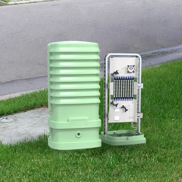
Cable Configurations, Lengths, and Splicing − This telecom pedestal is a combination of the plastic pedestal and metal bracket, the cable stud and Fiber optic box are not included. Splicing and dropping are required at the pedestal. Therefore, careful consideration should be given to determine the correct pedestal placement, as cables are not cut or prepared at the pedestal.
Pedestal Cable Stub Type and Select − The two cable stubs attached to the pedestal are either a dielectric or armored cable type, and the fiber inside the cable stub is either loose tube or ribbon fiber.
Place the backboard on the ground at the pedestal installation site. Use two people to carry the backboard (with the inner dome attached) and the attached cable stub bundles to the location where the pedestal will be installed. Always avoid any twisting or rotation of the stubs. Place the backboard on the ground at the site in the correct orientation (so each cable faces the proper feed/supply direction).
Unwrap the cable stubs. Remove the ties or wrapping that contain the coiled cable stubs and carefully unbundle and uncoil the long cable stubs. Making one large single loop or circle of the stub is suggested, to minimize cable twisting.
Attach base rear half to the backboard. Unlock and open the 2-piece base. Set aside the front half of the base. Place the rear half on the ground, inside facing up, just below the support bracket of the backboard. Align the support leg ends with the leg guides in the collar area of the base and slide the legs into the base leg guides (audible clicks indicate proper leg insertion)
Feed the cable stub ends into the conduit, trench, or vault. Without twisting the cable, pull the cable stub end into the conduit (for conduit applications). If an open trench is used, place the entire length of cable stub into the trench. If a vault is used, place the entire length of cable stub into the vault in the slack storage position. Minimize the twisting and pulling of the cable stubs to prevent any damage.
Lift, assemble, install, attach base front, and level the pedestal. Set the base at the proper depth to attach the front half of the base to the rear half, and to level the base.
Arrange the cable stubs in their final position. Place the cable stubs in their final position before backfilling, and support the stubs if/as needed.
Manage cable slack at splice point box. Manage any cable stub slack per company practice.
Backfill. Carefully backfill the trench (for open trench applications), then perform proper base backfilling and proper vapor barrier bag placement in the pedestal base during base backfilling
Manage cable slack at splice point box. Manage any cable stub slack per company practice. Splice cable stubs at nearby splice points, per company practice.End of pedestal placement.
Clean up site. If customer jumpers will not be installed at this time, clean up the installation site, and leave this document inside the pedestal (optionally with your notes written on it) for the next crew or installer.
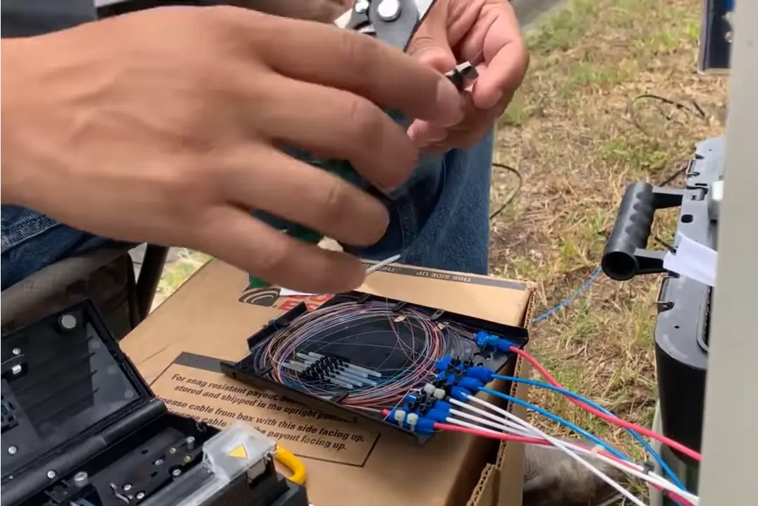
Jumpers − Customer connections are made via 2 mm, jacketed, 1 meter long, bend-insensitive jumpers (ITU−T G.657 Class A fiber), which activates the line when one connector of the jumper is inserted in the top bulkhead and the other connector is inserted in the bottom bulkhead.After installing the pedestal
What is ITU-T G.657
It is the aim of Recommendation ITU-T G.657 to support this optimization by recommending strongly improved bending performance compared with the existing ITU-T G.652 single-mode fiber and cables. This is done using two categories of single-mode fibers, one of which, category A, is fully compliant with the ITU-T G.652 single-mode fibers and can be deployed throughout the general transport network as well as the access network. The other, category B, is not necessarily compliant with Recommendation ITU-T G.652, but is capable of low values of macro bending losses at very low bend radii and is intended for application in the access network inside buildings or near buildings (e.g., outside building riser cabling). These category B fibers are system compatible with ITU-T G.657.A (and ITU-T G.652.D) fibers in access networks.
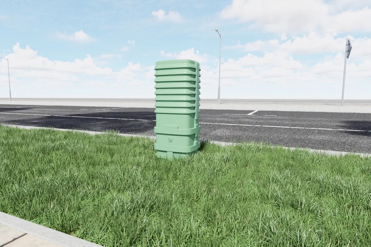
Jinmeng Telecom Pedestals are a combine of Rotational Molding Fabrication and HDPE plastic techniques that with excellent durability and UV resistance outdoor. The pedestals are the ideal solution for fiber optic droppings.